
BT1050 bottom blowdown timer for repeatable boiler operation
Spirax Sarco BT1050 is an electronic timer and controller for a boiler bottom blowdown valve. It schedules short valve-opening periods so precipitated solids can be discharged before they accumulate in the boiler. This is a different duty from continuous conductivity-based blowdown: BT1050 controls when the bottom valve opens, how long it remains open, and how multiple boilers are sequenced. The result is a defined operating routine that can replace inconsistent manual timing while preserving the need for a correctly sized valve, safe discharge arrangement and approved boiler-house procedure.
The controller contains three independent timer sequences. Each sequence can be assigned to selected days and given a start time, stop time, repeat interval and valve-open duration. One timer sequence operates at a time, and up to three scheduled periods can be configured in a day. This gives the operator enough flexibility to match the blowdown routine to shift patterns, changing boiler load or site operating policy without treating the controller as a continuous process regulator.
How scheduled bottom blowdown works
When a programmed blowdown is due, the BT1050 energises its control relay and the connected bottom blowdown valve opens for the configured duration. At the end of that duration the relay de-energises and the valve closes until the next valid schedule. If supply power falls outside the required range during a blowdown, the relay de-energises so the valve closes; when power returns after the scheduled period, the valve remains closed until the next programmed event.
The three timer sequences make it possible to combine different operating windows. A site could use one sequence for a weekday morning event, another for a later shift, and a third for selected high-load days. Start time must precede stop time, and the repeat interval defines whether the event happens once or repeats within the active window. These settings require a boiler-specific decision: the controller does not calculate how much sludge exists, the safe discharge duration, or the correct frequency. Those values must come from the boiler manufacturer, water-treatment programme, applicable regulations and the capacity of the installed blowdown system.
An optional valve switch box adds position feedback. When that input is configured, BT1050 can supervise whether the valve lifts from its seat and whether it closes within the allowed time. The associated alarm can be enabled and, if required by the operating philosophy, latched until authorised commissioning access is used. This feedback helps identify a valve that fails to move as commanded, but it does not replace inspection of the valve, actuator, wiring or discharge pipework.
Multi-boiler priority and recovery control
For multi-boiler rooms, Spirax Sarco BT1050 units can be linked so that no more than one boiler blows down at a time. The official instructions describe networks of up to nine BT1050 or compatible BT1000 timers. Each controller receives a priority value, and recovery logic delays the next discharge until the configured cooling period has elapsed. That coordination reduces the risk of simultaneous discharges overloading the downstream vessel or sending water to drain before it has cooled sufficiently.
The recovery timer is particularly important where several boilers share one blowdown vessel. It is an operating interlock between timer events, not a temperature measurement or a substitute for vessel sizing. The default recovery period in the manual is four hours, but the final value must reflect the actual vessel, boiler sequence, discharge quantity, cooling arrangement and site rules. A priority of zero indicates that a timer is not linked into the priority sequence; higher configured values determine which linked boiler is allowed to discharge first.
Operator interface and diagnostics
The front panel combines an LCD with a five-button keypad. In normal operation the display shows the current time, date or status information, the next timer event and any active recovery period. Alarm and error messages have priority on the information line, helping the operator distinguish a scheduled blowdown, a delayed event, a manual override, a valve-position fault or an internal data problem. The display can be set for black-on-white or white-on-black presentation.
A test menu supports controlled checks of the display, switch input, link input, valve relay and alarm relay. Manual output tests automatically return to normal control after the documented interval unless cancelled earlier. Commissioning access is password protected and the manufacturer states that the access code must be restricted to qualified, trained personnel. The public product information therefore describes the settings and safety boundary without publishing the commissioning code.
The clock calendar is backed by a replaceable lithium-thionyl-chloride battery. The documented battery supports the real-time schedule when mains power is unavailable, subject to its installation and service conditions. Battery replacement exposes the internal printed circuit board and must follow the manufacturer’s procedure, polarity instruction and disposal requirements; it is not a routine operator task.
Communications for boiler-control integration
Adjacent controllers can exchange data over a short-range infrared bus. A controller can be configured as an infrared master or slave, and an IR master fitted to an RS485 network can pass parameters from adjacent slaves to the wider communications system. The documented optical range is 10 cm with a 15-degree working angle, so the infrared path between units must remain unobstructed during panel layout and operation.
The wired interface supports EIA/TIA-485 in two-wire half-duplex or four-wire full-duplex form using Modbus RTU. The technical information gives a maximum cable length of 1,200 m with the specified screened twisted-pair cable; some Category 5 cable arrangements are limited to 600 m. Supported baud rates are 1,200, 9,600 and 19,200, with 9,600 as the documented default. Communications provide monitoring and integration data, but the local relay circuit and boiler safety functions still require independent installation and testing.
Electrical and environmental selection
BT1050 accepts a 110-240 Vac, 50/60 Hz supply. The technical data specifies a maximum power consumption of 7.5 W. Two single-pole changeover relays provide the valve-control and alarm outputs. Their documented maximum voltage is 250 Vac, with ratings of 3 A for a resistive load and 1 A for an inductive load at 250 Vac. Relay contacts must use the same phase as the mains supply, and the relay circuits require the overcurrent protection specified in the installation instructions.
The controller is for indoor use from 0 to 55 °C at altitudes up to 2,000 m. It can be mounted on DIN rail, on a chassis plate or through a panel cut-out. The installation must provide an industrial control panel or fireproof enclosure with at least IP54 environmental protection; the published IP65 and NEMA Type 4 hose-down ratings apply to the front panel within their approval scope, not automatically to the complete enclosure. Adjacent controllers require 15 mm cooling clearance, and the panel layout must minimise heat, vibration, shock and electrical interference.
The body is approximately 140 mm high, 120 mm deep and 52 mm wide at the front, with an approximate mass of 400 g. These dimensions help reserve panel space, but cable bends, terminal access, cooling clearances, the infrared line of sight and safe isolation space must also be included in the enclosure design.
Choosing BT1050 rather than a continuous blowdown controller
BT1050 is intended for timed bottom blowdown, where settled or precipitated solids are removed by briefly opening the valve at the base of the boiler. It does not measure boiler-water conductivity and does not modulate a surface blowdown valve. Where the primary requirement is dissolved-solids control based on conductivity, compare a dedicated product such as the BC3250 boiler blowdown controller. Some boiler houses need both functions, but each requires its own sensor, valve arrangement, commissioning basis and maintenance plan.
Selection must also account for the complete bottom blowdown installation. Confirm the boiler manufacturer’s recommended frequency and duration, the bottom blowdown valve and actuator, any position switch, the receiving vessel, cooling and venting capacity, drain route, electrical supply, enclosure, alarm philosophy and communications requirements. On a multi-boiler site, document the priority order and recovery period rather than accepting defaults without an engineering review.
Checks before ordering and commissioning
- Define the duty. Confirm that the application is timed bottom blowdown and establish the approved schedule from boiler and water-treatment requirements.
- Confirm the valve system. Verify the valve and actuator control voltage, relay load, safe failure position, opening duration and whether switch-box feedback is required.
- Review the discharge system. Check the blowdown vessel, cooling interval, any specified vent head, drain and vent capacity for the worst scheduled event and for the total number of connected boilers.
- Plan linked operation. Set the number of controllers, priority order, recovery period, infrared layout and RS485 architecture before wiring the panel.
- Confirm panel conditions. Provide the correct supply, overcurrent protection, disconnecting device, enclosure rating, cooling spacing and screened cable segregation.
- Control commissioning access. Assign trained personnel, retain the pass code securely, test the valve and alarm outputs, and record all timer, feedback and communication settings.
- Establish maintenance. Include battery condition, enclosure cleaning, valve operation, switch feedback, alarm testing and boiler blowdown practice in the site schedule.
For a correctly engineered system, Spirax Sarco BT1050 provides a repeatable real-time schedule, multi-boiler coordination, optional valve-position alarms and practical communications in one compact controller. Its value depends on disciplined commissioning: the timer settings, recovery logic and output tests must be based on the actual boiler installation rather than copied from an unrelated site.
Source note: this English web version is a faithful translation and consolidation of the official Chinese-language TI-P405-40 technical information. Installation and safety details are aligned with the English IM-P405-39 EMM Issue 7 instructions.
Description
The BT1050 is a timer for controlling the bottom blowdown valve on a steam boiler. Three independent timer sequences can define as many as three blowdown periods per day. A valve switch box may be connected so that an alarm is raised if the valve does not lift or close within the configured time.
For multi-boiler installations, up to nine BT1050 or compatible BT1000 timers can be linked. Priority and recovery settings prevent more than one boiler from blowing down at the same time and allow the shared blowdown vessel to cool between discharges.
Functions and interfaces
| Item | Documented function |
|---|---|
| Timer | Three independent sequences with selectable day, start time, stop time, repeat interval and valve-open duration. |
| Valve supervision | Optional switch-box input for valve lift and closing supervision. |
| Linked operation | Priority and recovery coordination for up to nine BT1050 or BT1000 units. |
| Operator interface | LCD and five-button keypad with run, alarm, test and password-controlled commissioning functions. |
| Local communications | Infrared link between adjacent controllers; master or slave configuration. |
| Network communications | EIA/TIA-485 with Modbus RTU. |
Power supply and environmental limits
| Supply | 110–240 Vac, 50/60 Hz |
|---|---|
| Power consumption | 7.5 W maximum in TI-P405-40 |
| Application | Indoor use only |
| Ambient temperature | 0–55 °C |
| Maximum altitude | 2,000 m |
| Overvoltage category | III |
| Pollution degree | 2 as supplied; 3 when installed in a suitable enclosure |
| Required enclosure | Industrial control panel or fireproof enclosure; minimum IP54, or the applicable UL50/NEMA equivalent stated in the source. |
| Front-panel sealing | IP65 and NEMA Type 4 hose-down protection within the stated approval scope; this does not rate the complete enclosure. |
Inputs and outputs
| Connection | Rating or function |
|---|---|
| Relay outputs | Two single-pole changeover relays; 250 Vac maximum; 3 A resistive or 1 A inductive at 250 Vac. |
| Switch input | For optional bottom blowdown valve position feedback. |
| Link input | For priority and recovery coordination between controllers. |
| Input open-circuit voltage | 32 Vdc maximum |
| Input pull-down voltage | 0.25 Vdc maximum |
| Input current | 1.5 mAdc maximum |
Communications
| RS485 physical layer | Four-wire full duplex or two-wire half duplex |
|---|---|
| Protocol | Modbus RTU |
| Isolation | 60 Vac/dc |
| Baud rates | 1,200, 9,600 or 19,200 baud; documented default 9,600 |
| Recommended RS485 cable | Screened twisted pair, 0.23 mm² (24 AWG); Alpha 6413 or 6414 is identified in the source. |
| Maximum RS485 cable length | 1,200 m (4,000 ft) with the specified cable. Listed Cat 5 arrangements are limited to 600 m. |
| Infrared interface | IrDA at 38,400 baud; 10 cm range and 15° working angle. |
Clock battery
The real-time clock uses a 3.6 V AA lithium-thionyl-chloride battery mounted on the printed circuit board. Replacement must be performed by competent personnel using the specified battery type and polarity, with disposal in accordance with local rules.
Mounting and dimensions
The controller supports DIN-rail, chassis-plate and panel mounting. Install it in a suitable enclosure that minimises heat, vibration, shock and electrical interference. Maintain at least 15 mm clearance between adjacent controllers for cooling and preserve the infrared line of sight where the optical link is used.
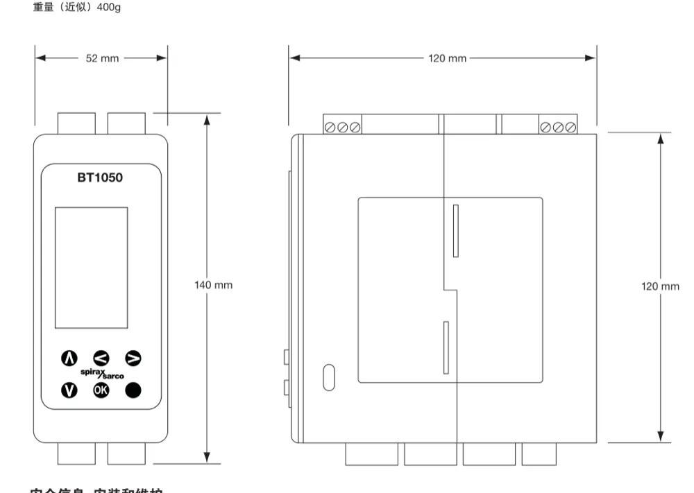
| Overall height | 140 mm |
|---|---|
| Overall depth | 120 mm |
| Front width | 52 mm |
| Approximate mass | 400 g |
| Controller-to-controller spacing | 15 mm minimum |
Allow additional space for cable bending, terminal access, isolation and ventilation. Use the current installation instructions when preparing the final panel cut-out and wiring layout.
1. Safety information
Safe operation depends on correct installation, commissioning, use and maintenance by qualified personnel in accordance with the instructions. Observe the applicable electrical, boiler-house, plant construction and local regulations, and use suitable tools and personal protective equipment.
- Isolate the mains supply before opening the enclosure, wiring terminals or removing the controller. Prove isolation before work starts.
- Provide a suitably rated disconnecting device and overcurrent protection. The disconnect must be close to the equipment, readily accessible and identified for the controller.
- Relay contacts must be supplied from the same phase as the controller mains supply. Do not use the equipment outside its published electrical and environmental limits.
- Assess the boiler, pressurised system, hot discharge, hazardous fluids and surrounding plant before work. Follow the site's permit-to-work and lockout procedures.
- Commissioning access is for qualified and trained personnel. Keep its pass code in a safe, access-controlled location; it is intentionally not reproduced here.
- After installation or maintenance, test the controller, valve, alarms and protective devices before returning the boiler to service.
2. Product and display
The BT1050 energises a relay to open the bottom blowdown valve when a programmed event is due. It closes the valve at the end of the selected duration. With an optional valve switch box, the controller can alarm if the valve does not lift or close in the configured time.
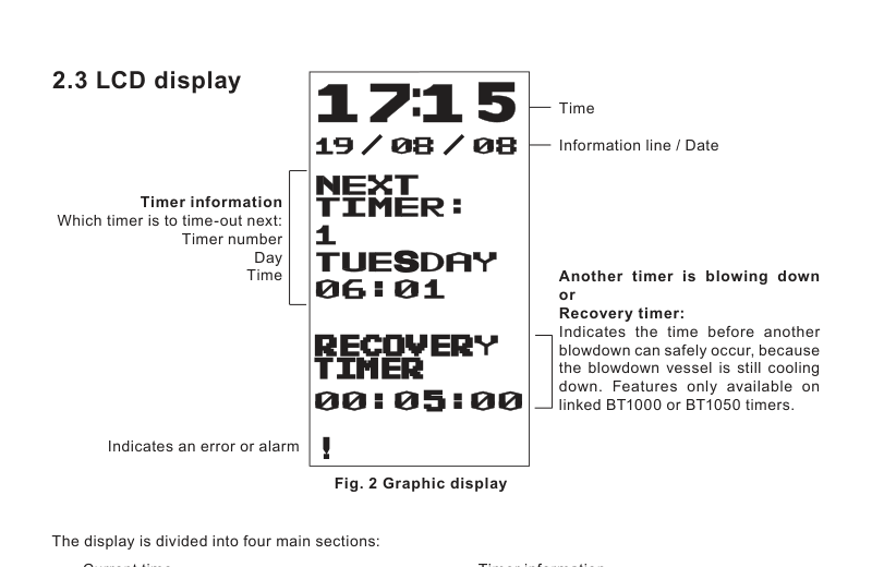
The run screens show time and date, timer status, next blowdown, recovery time and error messages. Alarm information takes priority. A flashing warning symbol indicates a stored error or alarm; clearing the message does not correct its cause, and a latching alarm remains active until authorised reset.
3. Operating principle
Three independent timer sequences can be assigned to days of the week. Each sequence uses a start time, stop time, repeat interval and valve-open duration. The start must precede the stop. Only one sequence operates at a time, and the configured schedule must come from the boiler manufacturer, water-treatment programme and site operating procedure.
Linked controllers use priority and recovery settings so that only one boiler discharges at a time. Up to nine BT1050 or compatible BT1000 units may participate. A priority of zero leaves the controller outside the linked sequence. Recovery time delays the next event to allow the shared blowdown vessel to cool; verify the final setting against the actual vessel and discharge duty.
4. Mechanical installation
- Check the controller and packaging for transit damage and confirm that the rating and intended duty are correct.
- Select an indoor location within 0–55 °C and below 2,000 m altitude, away from excessive heat, vibration, shock, moisture and electrical interference.
- Fit the controller in an industrial control panel or fireproof enclosure providing at least IP54 protection. Front-panel IP65 or NEMA Type 4 protection does not by itself rate the complete enclosure.
- Mount on 35 mm DIN rail, a chassis plate or through a prepared panel cut-out using the manufacturer’s clips and bezel arrangement.
- Leave at least 15 mm between controllers for cooling. Keep the adjacent infrared windows aligned, unobstructed and within their specified range if infrared communications are required.
- Provide enough clearance for conductors, terminal blocks, ventilation and safe access to the disconnecting device.
5. Electrical installation
All wiring must comply with the applicable EN, IEC and local standards. Separate mains and relay wiring from low-voltage input and communications cables. Use screened cable where specified, terminate screens according to the system design and avoid earth loops.
- Supply: 110–240 Vac, 50/60 Hz. The Issue 7 manual states approximately 30 mA at 230 V or 60 mA at 115 V; TI-P405-40 separately specifies 7.5 W maximum.
- Use conductors and terminal ferrules suited to the terminal blocks. For current installation work, follow IM-P405-39 Issue 7, including its 14 AWG maximum conductor guidance, rather than the older translated TI wording.
- Protect each relay circuit as instructed. Relay contacts are rated to 250 Vac maximum, 3 A resistive or 1 A inductive at 250 Vac.
- Wire the valve-position switch only when the fitted switch box and commissioning logic match the required lift and closing supervision.
- For linked boilers, daisy-chain the link input as shown in the official wiring diagrams; verify polarity, common reference and recovery design before energising.
- For RS485, use the required screened twisted-pair topology and termination. The interface supports two-wire half duplex or four-wire full duplex Modbus RTU.
6. Commissioning
Restrict commissioning mode to trained personnel. Before entering settings, confirm that the valve and discharge system are ready for operation and that opening the valve cannot expose personnel or equipment to an unsafe release.
- Set the clock, date format and display presentation.
- Select automatic operation and configure the three timer sequences as required: enabled days, start, stop, repeat and duration.
- For a multi-boiler installation, assign unique priorities and set a recovery period validated for the shared blowdown vessel.
- Configure switch-box monitoring only when feedback is wired. Set lift and closing supervision and decide whether the alarm must latch under the site's alarm philosophy.
- Set the communications address, baud rate, infrared master/slave role and RS485 mode to match the network design.
- Use the test menu to check the display, switch input, link input, valve relay and alarm relay. Output tests are time limited, but personnel must remain in control throughout.
- Return the controller to automatic run mode, confirm the next scheduled event, document all settings and secure commissioning access.
Manual ON can hold the valve open and manual OFF can suppress recorded times. Use either state only under an approved operating procedure and restore automatic operation when the test or intervention is complete.
7. Communications
Adjacent units communicate by infrared over a nominal 10 cm range and 15° working angle. One controller can act as infrared master and relay adjacent slave data through RS485. The wired interface uses Modbus RTU at 1,200, 9,600 or 19,200 baud. Use the network address and serial settings agreed for the control system.
Specified RS485 cable can extend to 1,200 m; the Cat 5 alternatives listed in the technical information are limited to 600 m. Network monitoring does not replace the local hardwired valve, alarm, isolation or boiler safety arrangements.
8. Maintenance
No routine internal servicing is required beyond the documented clock-battery replacement. Keep the front clean with a damp cloth and mild detergent; do not use solvents or allow liquid into the enclosure. Periodically verify the clock, schedule, valve travel, switch feedback, alarm relay, linked priority/recovery operation and communications.
The 3.6 V AA lithium-thionyl-chloride battery is mounted on the printed circuit board. Isolate power, observe electrostatic precautions and polarity, and use only the specified replacement. Do not short-circuit, recharge, puncture, crush, heat or incinerate the battery. Dispose of it under local regulations.
9. Fault finding
| Indication | Checks and response |
|---|---|
| Blank display | Check safe isolation, supply voltage, protective device, terminals and internal supply condition. Do not bypass protection. |
| Power failure message | Confirm the mains supply and clock. Review whether a scheduled event was missed and verify the next event before returning to automatic service. |
| Valve failed to lift or close | Make the boiler safe, then inspect relay command, actuator supply, valve mechanism, wiring and switch-box adjustment. Correct the cause before resetting a latching alarm. |
| Blowdown delayed | Check linked-controller priority, recovery timer and link wiring. A delayed event may be the intended result of recovery coordination. |
| No scheduled blowdown | Check automatic mode, clock and date, enabled days, start/stop window, repeat interval, duration, priority and active alarms. |
| RS485 or infrared data missing | Check address, baud rate, master/slave selection, two- or four-wire mode, polarity, termination, screening, cable length and optical alignment. |
| Data or internal error persists | Record the displayed message, isolate safely and contact competent service support. Do not continue operation if valve control or safety is uncertain. |
10. Decommissioning and disposal
Isolate electrical and process hazards before removal. Dispose of the controller and lithium battery separately in accordance with local and national requirements. When returning equipment, provide written details of contamination, residues and any health, safety or environmental hazards.